Living in a HOA governed community I have found my recent hotspot build assembly to have greatly extended my reach with ham radio while still abiding by the rules of the community.
The situation
So I live in a community governed by an HOA, which means I have certain rules I have to abide by and one of those important ones relates to antennas. More importantly that the HOA does not allow them, so that means as a ham radio operator I have to be more creative and stealthy about how I go about setting up my shack.
One of those ideas was to repurpose some of the Raspberry Pi boards that I have laying around the house. I had three Zero W boards I had a previous project in mind for but never got around to it and pretty much forgot I even had them until we were packing things up for the move into the new home. I also had a 3B that was going to be available to repurpose after the move, but I had a 4GB 4B that wasn’t being used that I could start off working with. I realized the 4B was very much overkill and it had a tendency to run really hot which made the 3B a much better option.
Collecting the parts
Thankfully I already had the Raspberry Pi boards which I’d purchased well before COVID-19 and chip shortages caused their prices to skyrocket. I think I paid $5-10 for the Zero W and $25-35 for the 3B. The 4B was around $45-55 as I recall for the 4GB model and I paid $75 for the 8GB model being used for my EmComm Server project. Now those prices are exceedingly high if I had to purchase them.
Besides the boards, I needed to get the MMDVM boards. As my primary radios I was going to be using were both of my Yaesu radios (FTM-400XDR & FT-70D) I needed to make sure the MMDVM supported the YSF (System Fusion/C4FM) digial voice mode. I got a simplex board for the Zero W and a duplex board for the 3B. While the Zero W was going to be my small mobile hotspot which I would need to run off of a battery pack, the power draw was going to be top factor to consider. My 16K mAh 2nd Gen Astro E5 Anker battery pack is more than enough power to run the Zero W hotspot for just over two days before needing to power down and recharge it. I was not as concerned with the 3B as it would have the standard AC power adapter.
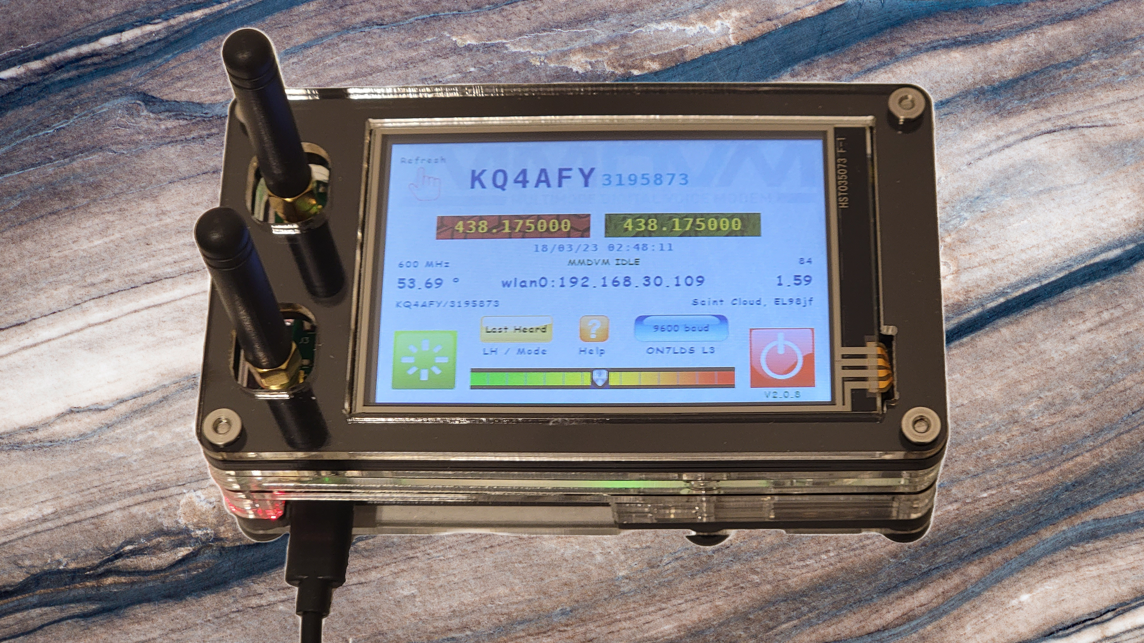
I found C4Labs had several really nice acrylic layered cases specifically designed for the Raspberry Pi and MMDVM boards so I got the JRZ-1S case for the simplex Zero W and the DRPi-3.5NSX case which include the 3.5" Enhanced Nextion screen for my 3B. The 3.5NSX case could also support the 4B with the Pimoroni Fan SHIM if I later find the 3B isn’t sufficient.
The left me needing the MMDVM boards themselves, for those I went with AURSINC who had both the simplex and duplex MMDVM boards that fit the C4Labs cases. Both boards supported P25, DMR, YSF, NXDN, DMR and D-Star digital voice modes and while both had an option to come with the OLED display I opted to go without it.
Some assembly required
Assembling the C4Labs cases was pretty easy and self-explanatory. Both came with easy to follow directions. The Zero W simplex build was probably the easiest and quickest of the two. If you had not already installed the header pins on the Zero W, this may take a little bit of added time. In my case I utilzed solderless headers from Adafruit that I have used on other projects before like my Ultimate GPS HAT for my NTP time server.
The DRPi-3.5NSX case for the 3B duplex build was also fairly easy with the only real complication being wiring in the Enhanced Nextion screen. This required me to break out the soldering iron so I could solder the four wire leads to the MMDVM board. The board was already designed to accept the Nextion or OLED displays, but required the wiring to be connected to the PCB. If you’re not comfortable with soldering then this may be something to get assistance from a fellow ham who is or wait until you have had some practice and feel more confident about it. Given the room in the case I cut the pin connectors off the wires and stripped a small amount so I could tin them. Then one-by-one I carefully soldered each of the four wires to their respective connector on the MMDVM board, making sure to swap the TX & RX wires.
There is a Facebook group devoted to Nextion screen designs for the
Pi-Star. I loaded several up into the Nextion Editor and output the TFT
file to try them out until I found the one I am working with currently.
It did require installing the ON7LDS NextionDriver and setting the Nextion Layout to ON7LDS L3 to run properly. Eventually I may try my
hand at developing my own but for now the one I have is functional.
Finishing touches
With the case assembled the only thing left to do is get the Pi-Star image loaded on to a microSD card, insert it into the Raspberry Pi and configure it. I used a 16GB SD card and downloaded the latest “Pi-Star_RPi” image from the download page. I used balena Etcher to write the image to the SD card after extracting the Pi-Star image file.
I got my information primarily from the Pi-Star website itself after reading through the various pages. There are YouTube videos out there that cover the topic but many are discussing older versions that may be dated.
When the Pi-Star comes online initially for the first time it is not
going to know your WiFi details, so this should be the first order of
business to tackle. Without a WiFi configuration the Pi-Star will default
to setting up it’s own AP WiFi SSID of Pi-Star-Setup that you can join
with your laptop/PC/mobile phone and use your web browser to access the
console at http://pi-star/. You’ll then be able to
configure the WiFi settings and restart your hotspot. While you could go
and continue with the configuration I find it best to reboot and bring
the hotspot back online using your WiFi rather than the default setup
WiFi SSID.
Once you have your hotspot on your WiFi network, the next matter to
address is the MMDVM board configuration. That is why we’re setting this
up afterall. The first step is to make sure it has the most recent
firmware. You can update it in one of two ways, the first is using an
SSH client to log into the Raspberry Pi shell or you can use the
SSH Access link under Configuration -> Expert. Either way you decide
to connect to the shell, you’ll want to run the command
sudo pistar-mmdvmhshatflash. With no options it will give you the usage
details. You’ll provide hs_hat or hs_dual_hat if using the same MMDVM
boards depending on whether you have the simplex or duplex model.
Before you can configure more you’ll need to make sure the Controller Software is set to MMDVMHost and the mode is sset to either simplex or
duplex depending on your board and click on Apply Changes. The next
key configuration to make after that is applied is the Radio/Modem Type
to let Pi-Star know what you have. I’ve set mine to MMDVM_HS_Dual_Band for Pi (GPIO) and had good success but mileage may vary so may need to
use one of the others as long as it says MMDVM_HS and for Pi (GPIO).
Once the MMDVM is configured the rest of the configuration is really just
a matter of personal taste. You can now enable the digital modes needed
for you. In my case that consisted of YSF since I’m using Yaesu radios,
but I did include the YSF2DMR cross-mode. I would recommend limiting
modes and not trying to run multi-mode, if you have different radios that
support D-Star and DMR. I would configure the hotspot for one mode and
setup another hotspt for the other. You will need to run them on
different frequences if you want to have them online at the same time though.
Some of the digital modes you will also need to be registered before you
can use them so you’ll need to look into that additionaly. You also need
to ensure your licensed callsign is properly entered for the Node Callsign.
